Project Development
In this page, I will:
Briefly describe my team chemical device
Show how the team planned, allocated the tasks, and executed the project.
Document the entire design and build process of the chemical device and include videos, pictures, and screen captures of the processes.
Include “Hero shot” of every milestone of the processes, example the part A that was 3D printed, part B that was laser-cut, electronics components moved/worked according to the program. Hero-shot is taken with the person-in-charge holding/working/making the parts.
Include the name of the person who was in-charge of every part of the project.
Document my individual contribution to this project.
Provide the link to the page of the blog of my teammates.
Describe problems encountered and how the team solved them.
Include all the project design files as downloadable files.
Embed the final prototype design file, i.e., the final fusion360 design file showing the entire prototype.
Type my Learning reflection on the overall project development.
Our team Chemical Device
In this section, I will briefly describe my team chemical device.
Before I introduce my team's chemical device, I would first like to share abit of background information on the seriousness of the issue. Since our product is a breathanalyser made to prevent accidents from driving under the influence of alcohol, we did some background research on this issue. There is actually multiple common causes of road accidents including distracted driving, speeding, poor maintenance of the vehicle, unsafe behaviour on the road and driving under the influence of alcohol. We then decided to dive deeper into the last point and found some interesting stats. According to the SPF and CNA, there has been an overall increase in drink driving arrest from 2021 to 2022 and the amount of deaths from drink driving accidents have doubled in 2022 as compared to 2021
Therefore , we decided to tackle the issue on how to prevent drunk driving accidents. We then made our project statement ' How do we prevent drivers in Singapore from driving under the influence of alcohol?'
What it is. What problems will the chemical device solve?
Our device is targeted at preventing people from driving when they are drunk, preventing accidents and potential deaths from drunk driving. This breathanalyzer has a pulley mechanism integrated in the design. This pulley system has a cover which is blocking the keyhole, preventing the user from driving immediately. This thus forces the user to breathe into the breathanalyzer if they do want to drive. If the alcohol sensor detects too high of an alcohol level, the cover won't come up, preventing the user from inserting their key. Only when the alcohol level is low, the pulley mechanism would then pull up the cover, allowing the user to drive off. This mechanism forces the user to use the breathanalyzer if they do want to drive and hopefully preventing more drunk driving accidents.
Our breathanalyzer also includes a temperature sensor which other breathanalyzers don't have. This allows for more accurate results as normal breathanalyzers tend to become less accurate the more times it is being used. By integrating this temperature sensor into our breathanalyzer, the results would become more accurate thus preventing more drunk driving incidents from happening.
Below is the hand sketch of the chemical device.

Team Planning, allocation, and execution
In this section, I will list down my team member's name and their respective roles (CEO, CFO, COO, CSO)
Sreenithi (CEO)
Jun Yi (COO)
Ahbishek (CFO)
EngKiat & Matthias (CSO)
This is our finalized BOM table.

Finalized Gantt Chart
Task Allocation
Me & Sreenithi (Fusion 360 & Laser Cutting)
Jun Yi & Ahbishek (Arduino)
Matthias (3D Printing)
All of us (Assembly)
Design and Build Process
In this section, I will provide documentation of the design and build process.
Part 1. Design and Build of Reusable Mouthpiece and Laser Cutting (done by Sreenithi)
Documentation for task 1.
Part 2. Design of breathanalyser body and laser cutting (done by me)
Documentation for task 2.
Hero shot for task 2.
Part 3. Arduino Programming (done by Jun Yi and Ahbishek)
Documentation for task 3.
Part 5. Integration of all parts and electronics (done by all)
Embed the finalized fusion 360 design files.
Documentation for integration.
Hero shot for integration.
Link to my groupmates blog:
- Sreenithi: http://cp5070-2022-2b02-group1-sreenithi.blogspot.com/
- Jun Yi: https://jylai21.wixsite.com/cp5070-2022-2b02-gro
- Matthias: https://matthiasnglokyi.wixsite.com/cp5070-2022-2b02-mat
- Ahbishek: http://cp5070-2022-2b02-group1-abhishek.blogspot.com
Brainstorming:
When we were given the green light to start on our prototype, we first had to decide on our dimensions for our prototype. Since we had 4 components to include: LCD, alcohol sensor, temperature sensor and a servo, we then decided to use 2 arduino boards so that we could link all the 4 components. Once all that was done, we then had to decide how we would want to assemble our prototype. Since we had 2 arduino boards and a breadboard, we decided to place them one on top of the other and measure the length and the breadth. We then used that measurement to decide on our dimensions for our prototype. So once we’ve finalised on our dimensions, we then had to decide which parts we had to 3D print and laser cut since there was a requirement that 3D printing and laser cutting has to be integrated into our prototype. After some discussion, we decided to 3D print our mouthpiece and laser cut the case of our prototype. While that was happening, Mr Chua then said that there has to be a mechanism that is connected to our prototype. This kind of shocked us as we were not informed of such a requirement until then. We then had to think on the spot of a quick mechanism that we could integrate into our design as we didn’t want to delay our design process. Jun Yi, my groupmate, suggested using a pulley as our mechanism. The pulley would then be connected to 2 things: a servo and a piece of cardboard. The servo was incharge of turning the pulley while the piece of cardboard would be lifted up by the pulley to block the keyhole of the car. All of this is enabled by using string to connect the servo, pulley and the cardboard piece together.
Once all of that was settled, we then had to split our task equally amongst ourselves as there was quite a lot to do. After some time, we decided on the following: Sreenithi and myself would work on the fusion for the designs of the breathalyser and the mouthpiece. Jun Yi and Ahbishek would work on the arduino coding while Matthias would work on the mechanism. With all that decided, we could then move onto the design making process.
So this was our initial sketch of our breathanalyser:
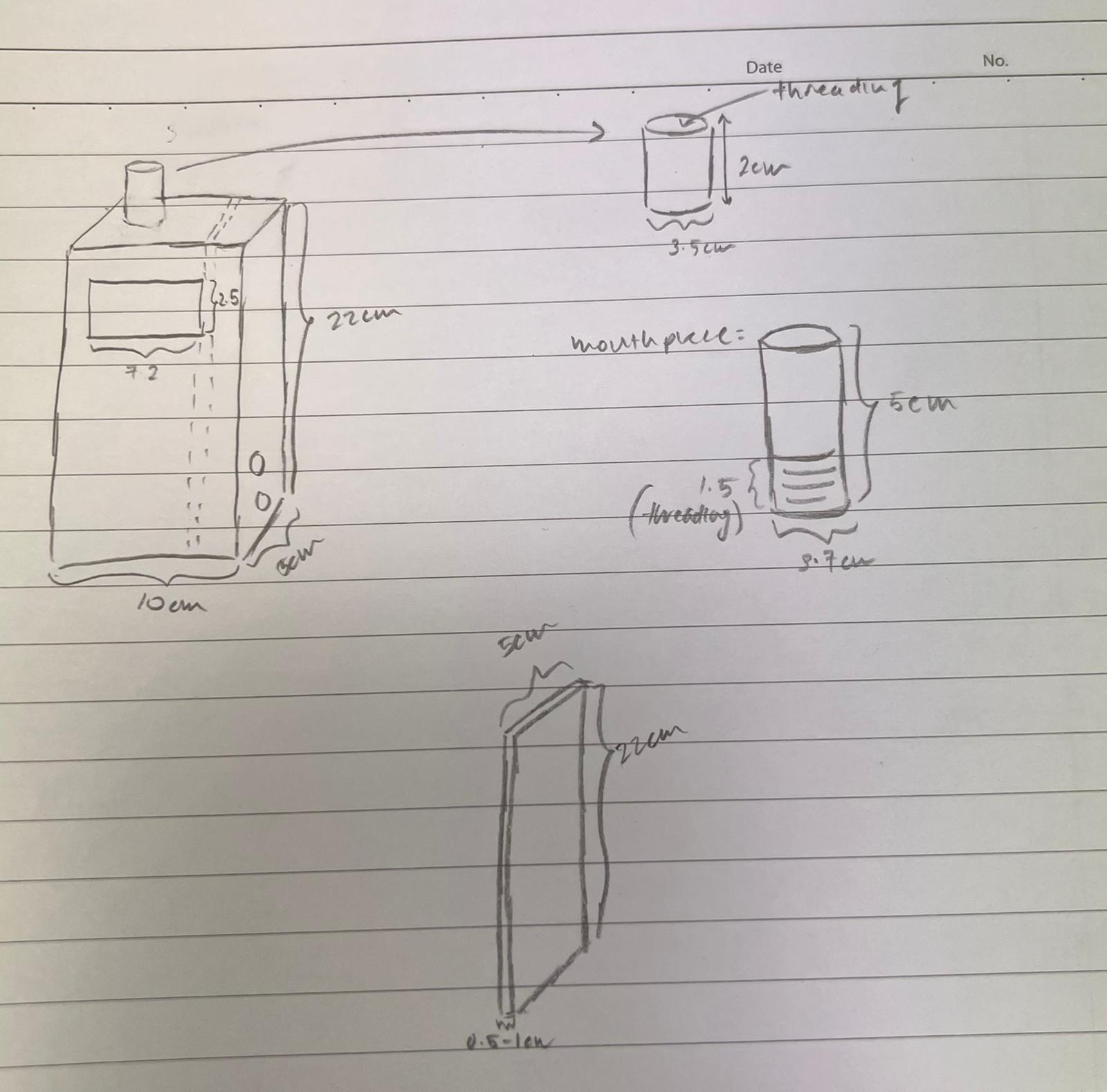
However, when we transferred this design onto Fusion 360, we realised that the dimensions of the mouthpiece could be further modified to make it fit the breathanalyser better as the initial dimensions for the mouthpiece was too huge and when we 3D printed it, we realised that it was too big to fit onto the top of the breathanalyser.
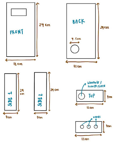
So after some modifications, this was our final sketch:

Moving onto our mechanism, we decided to make our mechanism out of cardboard as it was the most readily available resource. We first had to make the ‘pulley’ thing itself. We cut out 2 identical sized cardboard circles and then used our failed 3D printed mouthpiece to connect them all together. We then added a skewer through the 2 circles and hot glued it together. Once that was done, we then made a small rectangular piece with a small circle cut into it to simulate the keyhole of the car. We then used the cutout of that small circle and used that as our keyhole cover since it was a perfect fit. We then used string to connect the keyhole cover, pulley and the servo together.
This is how our mechanism turned:

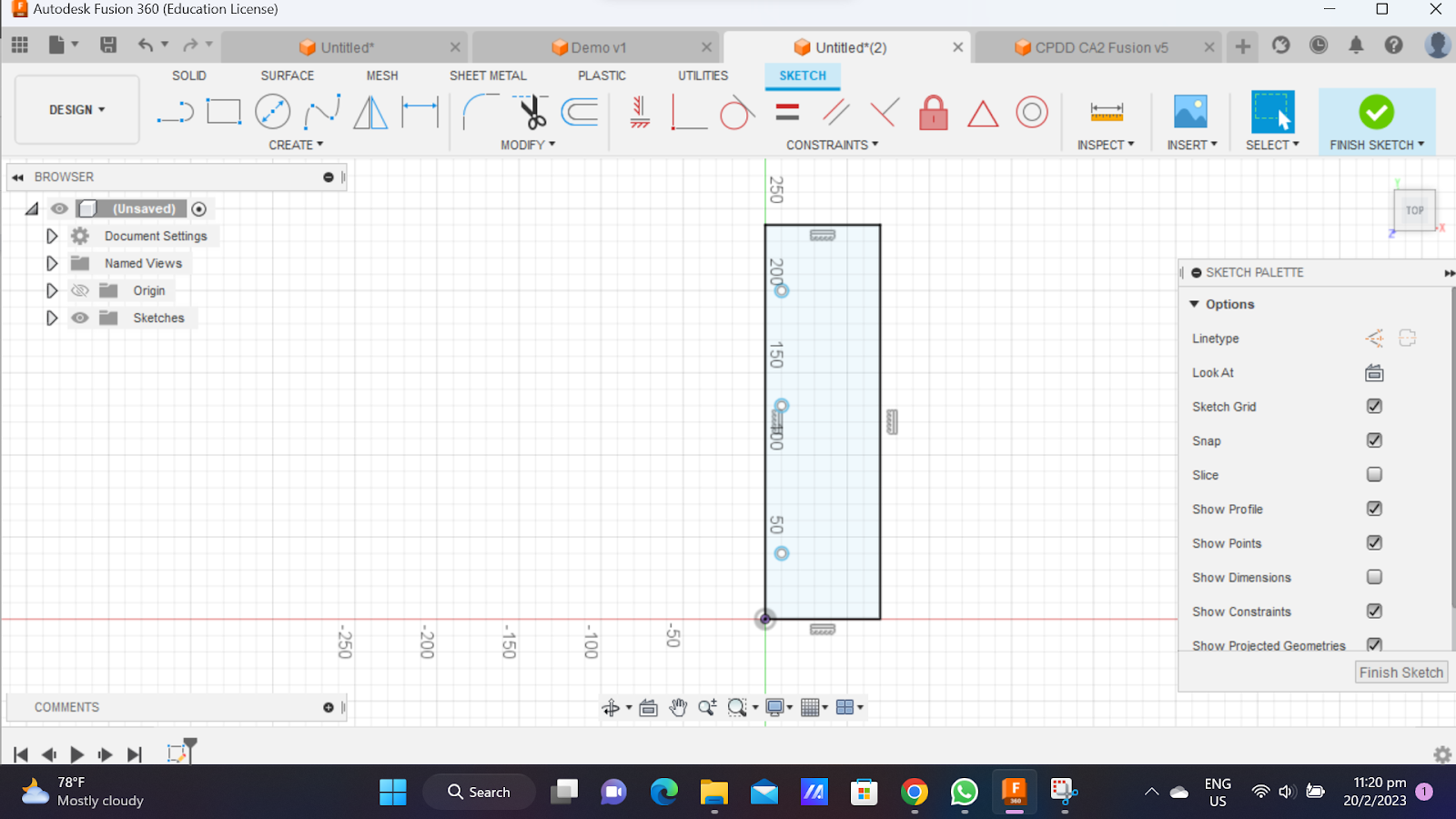
Fusion 360
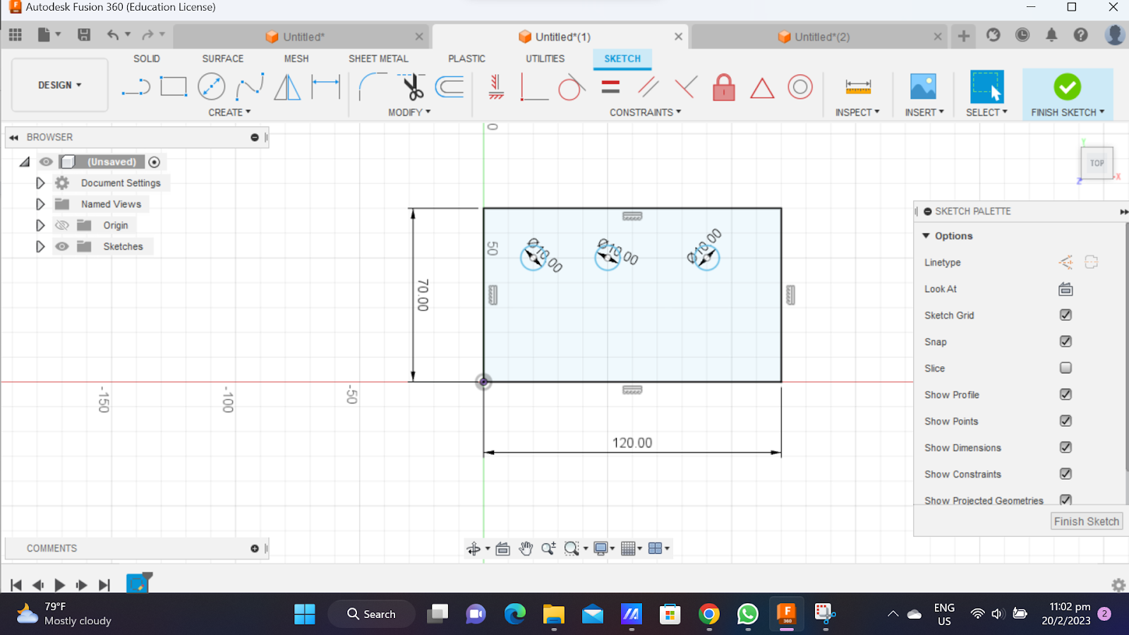
Now, I would be documenting the Fusion 360 process for the case of the breathanalyzer. Since this is made for laser cutting, there is no need for extruding the sketch.
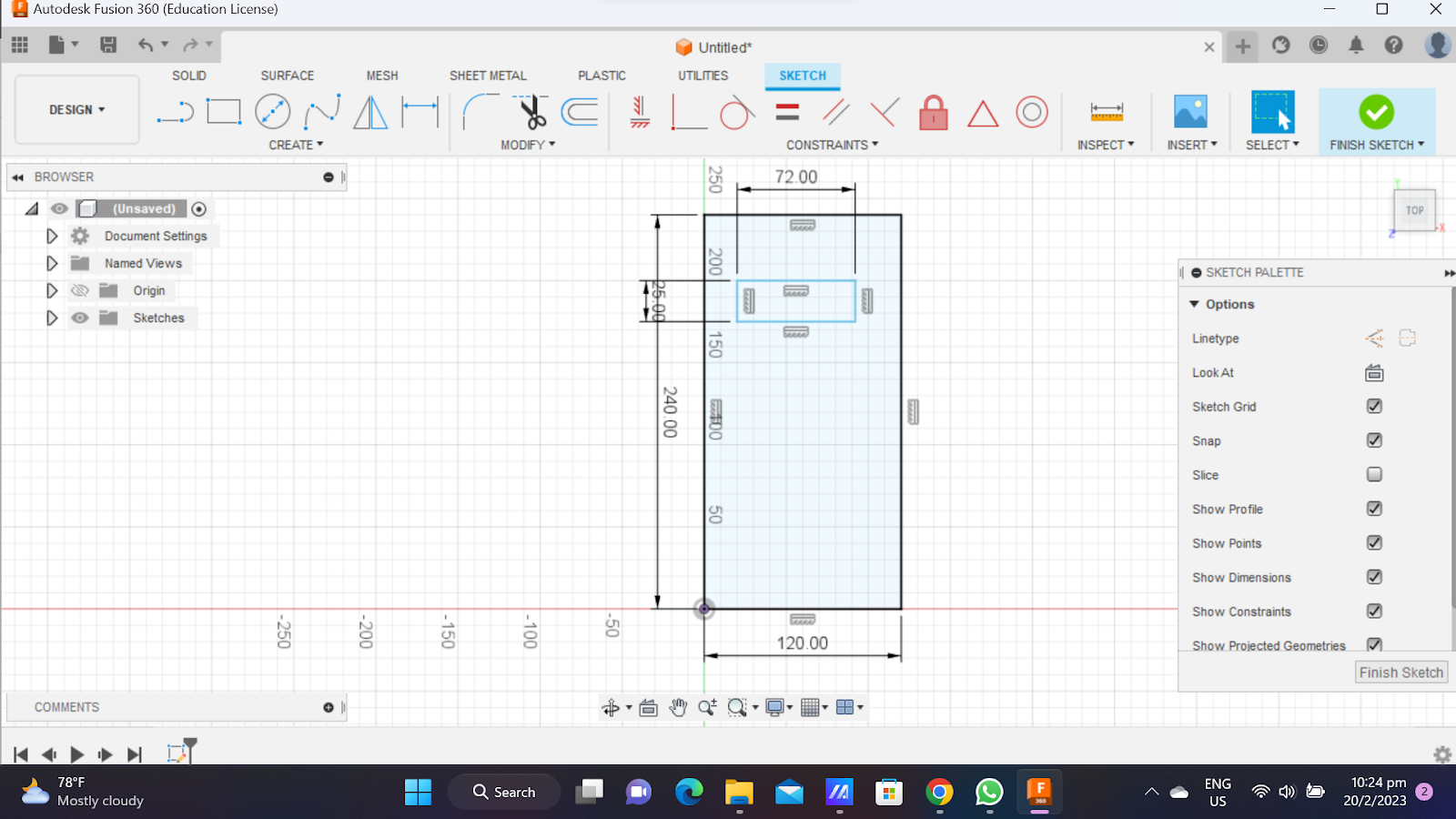
Front:
First, I created a 12 cm by 24 cm rectangle

Next, I made a 7.2 cm by 2.5 cm rectangle in the middle. This serves to fit the LCD so that the display can be seen
Back
SInce the back and the front should have the same dimensions, I created the same 12 cm by 24 cm rectangle.
Next,to allow the arduino wire to connect to our laptop, we had to create a hole at the back to allow the wire to escape. The hole has a diameter of 4.5 cm

Top
For the top, I first made a 12 cm by 7 cm rectangle.
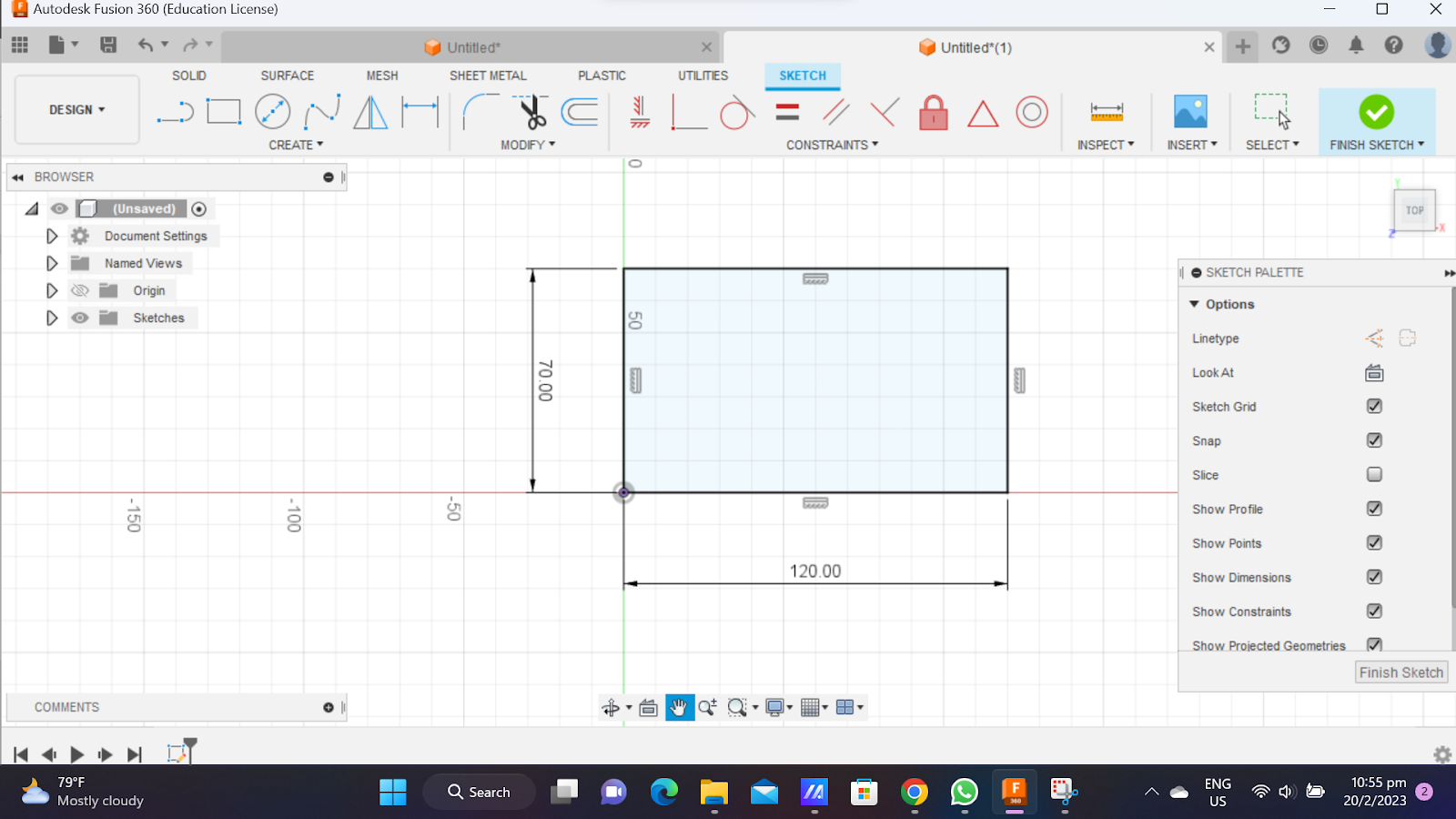
Next, I made a 2.5 cm diameter circle. This circle allows the breath from the mouthpiece to come into contact with the alcohol sensor.

Side
For the sides, I made a 24 cm by 7 cm rectangle. This piece has to be laser cut twice to serve as both sides of the case.

Bottom
For the bottom, I first made a 12 cm by 7 cm rectangle.
Then, I made 3 1cm diameter circles to simulate vents.
Now that all the parts were done, select ‘Export’ and select .dxf as the file type.

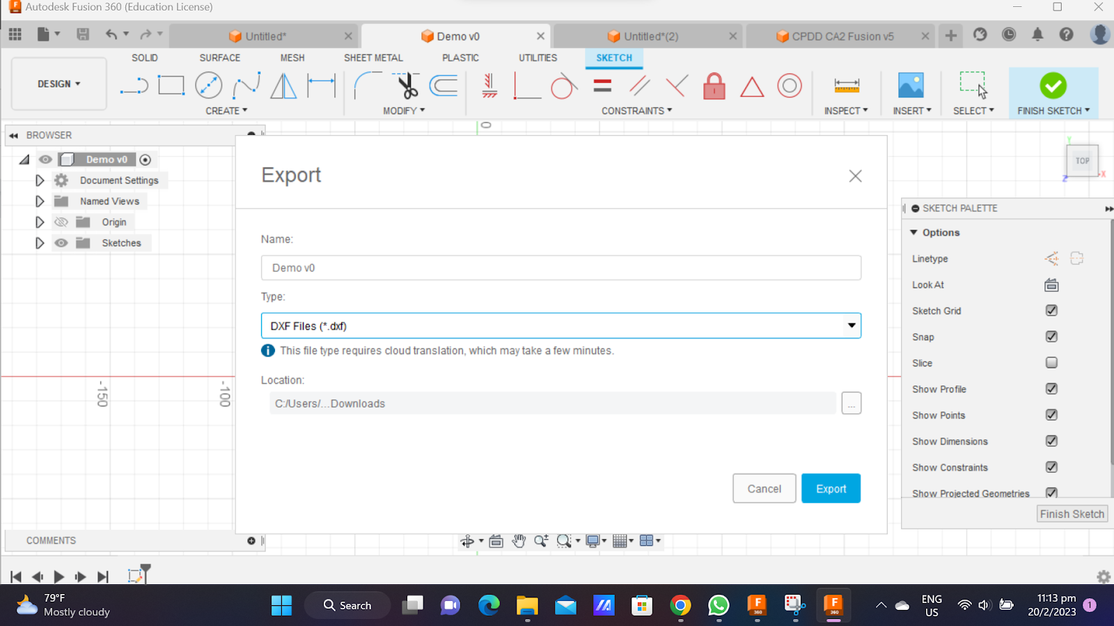
And, with that, we are done with Fusion360.
Hero shot with the design:

Project Integration
Once everyone has done their assigned task, we then met up to assemble our prototype. We first had to assemble the casing first using acrylic glue. This process was quite easy as it was just a waiting game. Once that was done, we then decided to attach the mouthpiece to the case first as it was the easiest.


Once the mouthpiece was done, we then decided to tackle the hardest part: the Arduino. Assembling the Arduino took us some time as we wanted to minimize the wires from getting tangled. After some time we managed to assemble it in a way that has the lowest chance of the wires bring tangled.
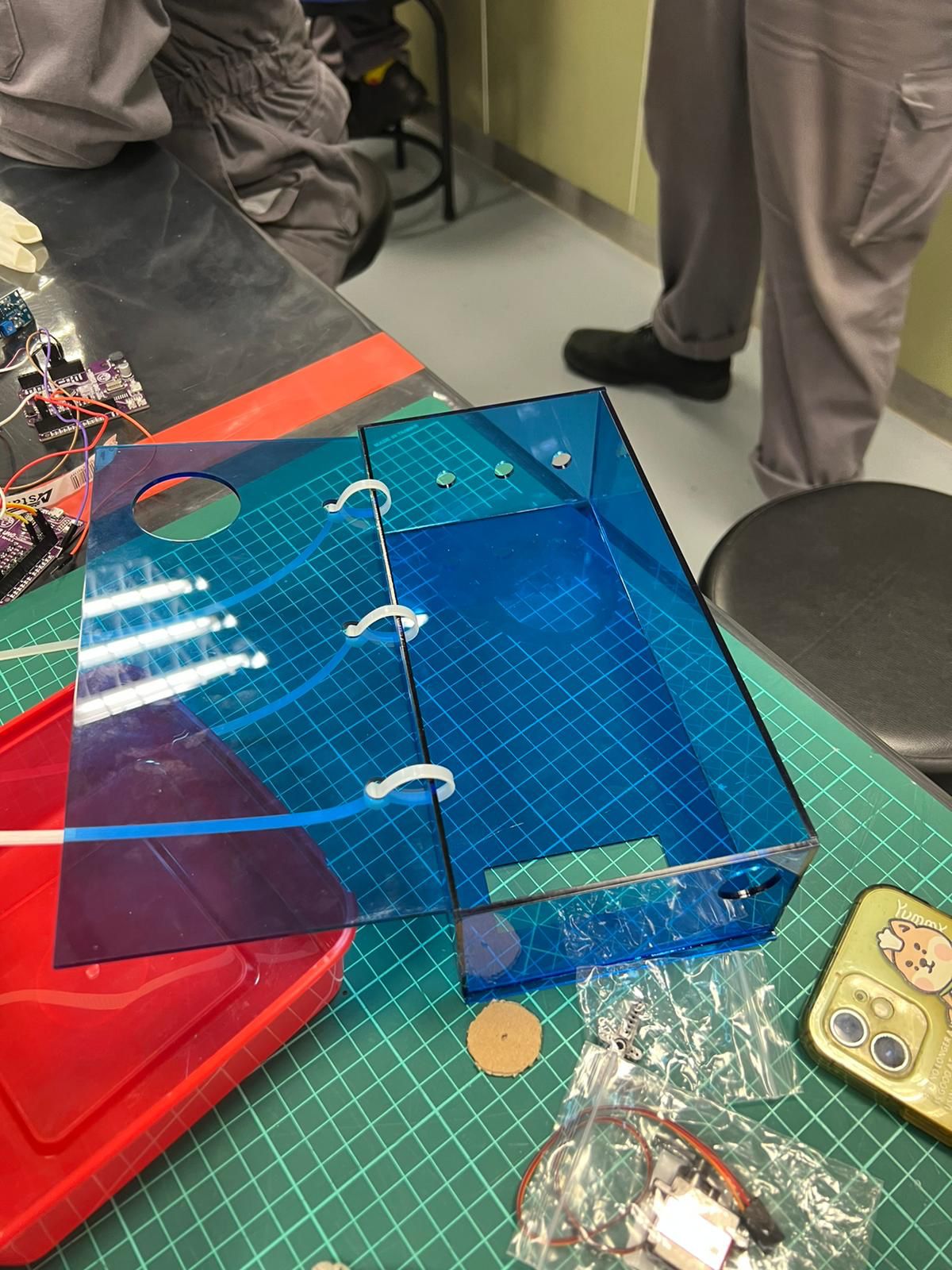
And with that done, connecting the mechanism to our prototype was as they are connected via a servo and since our mechanism is a external mechanism, meaning that it was actually outside of the prototype, all we had to do was to connect the servo to the breathanalyser and we're done!!
This is how our final product actually looked like:
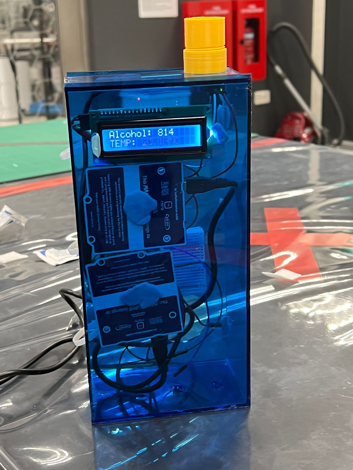

(Front view) (Top View)


(Side View) (Back View)
Problems and solutions
In this section I will describe the problems encountered in the design and build process and how the team solved them.
Problem 1:
While assembling our product, we weren’t sure if we should use acrylic glue on all 6 parts of our case. Since all of our components are connected to the case via bluetack, if we glued al 6 sides and one of our components fell, we had no way to put it back. So what we did was we decided to use cable ties to simulate hinges so that we could have easy access to the interior of the breathanalyser. However, in order to do this, we had to make holes to fit the cable ties through so we had to redesign the one side and the back to accommodate for the cable ties. We decided to make 3 8mm holes on the sides and back to make room for the cable ties.
This is our modified side:
This is our modified back

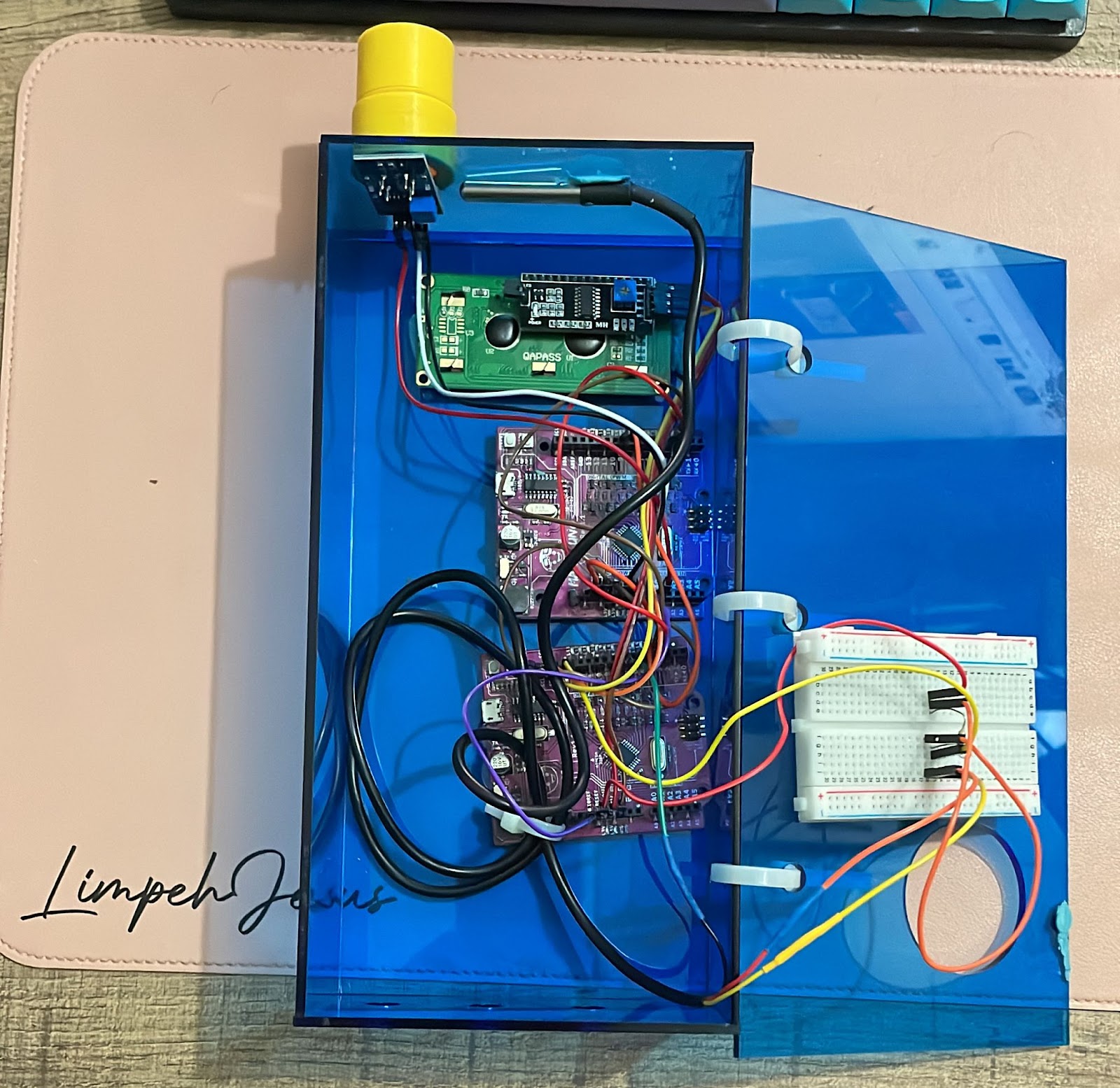
Problem 2
Since we were using 2 arduino boards, there were alot of wires that we used since apart from the 2 arduino boards, we also had an alcohol sensor, temperature sensor, LCD and a breadboard. This meant that we had to change the way we assembled our arduino. Initially, we wanted to place them on the back piece of the case. However, after looking at the amount of wires we had, we then decided to place the 2 arduino boards on the front piece with the breadboard at the back. This arrangement minimises the chances the wires have to be tangled with each other.
Problem 3
When we were constructing our pulley system, it was quite difficult to find the optimal length between the servo, pulley and the keyhole cover. This was quite troublesome as we really had to use a lot of trial and error to find the length. Since the main connection point is the pulley itself, we first had to find the point where the keyhole cover had enough length and then connect the pulley to the big piece of cardboard. From there, we just modified the length of the string connecting the servo and the pulley.
Project Design Files as downloadable files
In this section, I will provide all the design files (Fusion360 files, .dxf files, .stl files, arduino programs files) as downloadable files.
https://drive.google.com/drive/folders/1CrlALAeOfzeJmCTNVM-NaieptvTDgiua?usp=share_link
Below is my Learning Reflection on the overall Project Development
This entire journey for this project development has been a very eye opening one as I was exposed to a lot of new things that I wouldn’t have been exposed to without this module. For starters, laser cutting was very new to me and having to use it for this project made me more confident for the future when I have to laser cut again. While on the topic of laser cutting, using things like acrylic glue was also new as I didn’t even know such things existed prior to this.
This whole process has also allowed me to put my knowledge on Fusion360 from ICPD to good use as it was very necessary since our entire prototype required us using Fusion360 to design our prototype. This process has also shown me the importance of time management when doing a project of this standard as without proper time management, we wouldn't have been able to complete it in time and would require us staying back unnecessarily if only we had proper time management. I also learnt the importance of work delegation as since our prototype had quite a few components, by proper delegation of work, we were able to work on multiple things simultaneously which meant that we were quite efficient in that aspect and thus had more time to focus on the more important things such as the assembly.
Overall, this project kind of lets me know how Capstone would be like and allows me to prepare myself for when the time comes. This thus concludes my CPDD journey. it has been a bumpy journey with lots of ups and downs but we managed to make it till the end. Huge thanks to my group and thank you for reading this far!!
Comments
Post a Comment